Bootloader EEPROM: upgrade and lock
Every Raspberry Pi since the Pi 4 keeps its bootloader and the bootloader’s settings in a small flash chip on the board, the bootloader EEPROM. On a fleet Pi that chip is locked, so that nobody with root on the Pi can change how it boots; a new bootloader therefore cannot simply be installed. Which machine do you have?
A Raspberry Pi 5: check, upgrade and lock. Is its bootloader the fleet’s, and is it locked? (The check.) If not, six steps for someone with the Pi in hand (the upgrade).
A Compute Module 4 or 5 in a Compute Blade: does it need anything? How to tell (the two blades we read need nothing). There are no upgrade steps for it.
The rest of this page is what has been run and measured, what is not known and what does not work.
What is behind these pages
You do not need this part to do the job.
What has been run
Upgrade of a locked Pi 5, steps 2 to 6: on three fleet Pi 5s at Welland, none of them exactly as written here: one on 3 Oct 2026, and the Pis under acorn-olive and acorn-sycamore, written by hand on the bench on 5 or 6 Oct 2026 with a recovery card of their own. How those cards were made was not recorded. Both of these Pis had read
2026/05/26on 4 Oct; both read2026/09/25andBOOT_ORDER=0xf2after the write.The lock coming back on a normal port, steps 5 and 6: seen on both Pis of 6 Oct. Each sat on the site’s EEPROM service port after its write and read
SR1 0x0there (acorn-olive’s Pi at 09:17, acorn-sycamore’s at 10:21, 6 Oct). Each was then moved to a normal port and readSR1 0xbc40 seconds (acorn-olive’s, 10:12) and 100 seconds (acorn-sycamore’s, 10:58) after a start there began. Neither Pi was watched between its two reads, so whether that was its first start on the normal port is not known. The Pi of 3 Oct read locked when next looked at.The times in the steps (at least 60 seconds and at most five minutes for the write, two minutes for the start, five minutes before calling a Pi gone) are generous round figures of ours, not measurements of the write. The two minutes of step 5 cover the 40 and 100 seconds above.
Step 1: the commands up to the four files were run on a PC on 5 Oct 2026 (raspberrypi/rpi-eeprom at commit
a72213d, fetched withgit clone --depth 1on the day that commit was its newest); the outputs shown are from that run. Formatting a card and booting a Pi from a card made this way: not yet run by us.The check: the outputs shown are what acorn-olive’s Pi printed on 6 Oct 2026 after its upgrade, line for line (
vcgencmdat 09:17, the read script at 10:12). The read script is this page’s file as published, fed to the Pi over ssh (sudo python3 - < read_flash_status.py), on both Pis of 6 Oct. Typing it in withcatin the web terminal, the other way the check gives, has not been run by us.The board page and its web terminal have no picture on this page yet.
The pictures of the bridge are drawn on a photo. We have no photo of a real bridge, of a card going in, or of the LED during a write.
The LED during the write: Raspberry Pi’s documentation says a steady rapid blink means success and an error pattern means failure. On the run of 3 Oct it blinked 3 long, 3 short, an error pattern, although the write had succeeded (on 5 and 6 Oct the LED was not recorded). Step 4 trusts the rapid flash as success (the project owner’s choice, 7 Oct 2026) and, for an error pattern, sends the reader on to step 6’s read-back rather than back to the start.
How step 4 knows the write is over: by Raspberry Pi’s rapid green flash, which its documentation gives as success for an image called
pieeprom.bin(quoted below); the project owner chose it on 7 Oct 2026. How long the write takes has not been timed by us: step 4’s “at least 60 seconds” is a round figure of ours. The read-back of step 6 still decides.Three rows of the step 6 chart (“but BOOT_ORDER is not 0xf2”, “but SR1 0x0” and “no answer”): not seen by us. A Pi that is written but not locked can be changed by anyone with root on it, which on a public site is every visitor: that is why its row says to tell whoever runs the site if it stays unlocked.
That a Pi 5 runs
recovery.binfrom a card whatever its flash holds is Raspberry Pi’s documentation, not yet needed and so not yet run by us.Compute Module, Compute Blade: only the two reads. Nothing that changes a bootloader has been run by us on that hardware.
What two fleet Pi 5s printed
A Pi that still needed the upgrade, 4 Oct 2026, beside the done one shown in the check:
$ vcgencmd bootloader_version
2026/05/26 16:01:25
version 086b83e3332dfc8927c56762771d082f3077a1ae (release)
timestamp 1779807685
update-time 0
capabilities 0x0000007f
$ vcgencmd bootloader_config
[all]
BOOT_UART=1
BOOT_ORDER=0xf12
NET_INSTALL_AT_POWER_ON=1
sudo rpi-eeprom-update printed BOOTLOADER: up to date on both: it compares
with the package installed in the root, not with what the fleet wants. Of
the two blades read at ps1 on 5 Oct 2026, pi16 at ps1 printed what the
Compute Module page shows; pi20 at ps1
printed 2025/11/05 17:37:18 and the same settings.
The lock, bit by bit
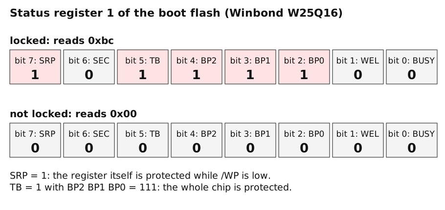
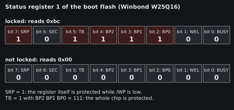
The script prints 0x00 as 0x0. The W25Q16JV datasheet also says that with
QE = 1, as these flashes have, the /WP pin is not used; what that means for
the lock is under Not yet known.
Why the flash is locked
See EEPROM write protect.
What was measured on the Pi 5
All of it on Pi 5 boards with the W25Q16 flash, netbooting the fleet root, on 3 and 4 Oct 2026. Observations 2 to 5 are from one board.
Observation |
|
|---|---|
1 |
|
2 |
|
3 |
With the flash protected, the netboot self-update fetched |
4 |
An SD card holding |
5 |
With the flash unprotected and already holding the offered image, the netboot self-update found nothing to do and booted on. |
6 |
The flash’s |
7 |
A bootloader of |
Observation 1 does not fit a plain reading of Raspberry Pi’s description
(quoted further down), where the setting is “for recovery.bin”: the bootloader applied it from
a netbooted config.txt. For observation 2 the simplest explanation is a bridge
that was not making contact; the other is that the bootloader sets but does not
clear the protection outside recovery.bin. Which it is has not been found out
(the bootloader’s UART log during such a boot has not been captured), so an
unlock over netboot is not shown to work, and not shown to be impossible.
Not yet known
Whether the lock holds against root on the Pi. Raspberry Pi’s documentation says the Pi 5’s
/WPpin is low by default, so the status register cannot be changed without bridging the pads. The W25Q16JV datasheet says that withQE=1(which these flashes have) the/WPfunction is disabled. If the datasheet is right, root could clear the protection with two SPI commands. Nobody has tried it. Until it is tried, treat the lock as protection against accident and against the standard tools, not as proven against a determined visitor.Whether the SD card route works without the bridge.
Whether
eeprom_write_protect=0over netboot unlocks a Pi 5 whose bridge is known to be fitted (observation 2).What
rpi-eeprom-update -aorrpi-eeprom-config --applydoes on a locked, netbooted fleet Pi. Neither has been run by us there.Whether a Pi 5 that does not boot any more is repaired by the same card. Raspberry Pi documents that it is (below); we have not had such a board.
What does not work
A netboot self-update against the protected flash: nothing is written and nothing reports it (observation 3).
rpi-eeprom-update -aandrpi-eeprom-config --applystage the same kind of update for the bootloader to apply, so the same outcome is expected; not yet run by us.Serving
eeprom_write_protect=0to the Pi over netboot did not unlock it when tried, with the caveat of observation 2.flashrom: Raspberry Pi’s documentation says it “does not support clearing of the write-protect regions and will fail to update the EEPROM if write-protect regions are defined”.
What Raspberry Pi says (Pi 4 and Pi 5)
From the config.txt documentation,
eeprom_write_protect:
Configures the EEPROM
write status register. This can be set either to mark the entire EEPROM as write-protected, or to clear write-protection.This option must be used in conjunction with the EEPROM
/WPpin which controls updates to the EEPROMWrite Status Register. Pulling/WPlow (CM4EEPROM_nWPor on a Raspberry Pi 4TP5) does NOT write-protect the EEPROM unless theWrite Status Registerhas also been configured.[…]
eeprom_write_protectsettings inconfig.txtforrecovery.bin.[…]
On Raspberry Pi 5
/WPis pulled low by default and consequently write-protect is enabled as soon as theWrite Status Registeris configured. To clear write-protect pull/WPhigh by connectingTP14andTP1.
Values: 1 protects the whole EEPROM, 0 clears the protection, -1 (the
default) does nothing.
From Raspberry Pi boot EEPROM,
recovery.bin:
At power on, the ROM found on BCM2711 and BCM2712 looks for a file called
recovery.binin the root directory of the boot partition on the SD card. If a validrecovery.binis found then the ROM executes this instead of the contents of the EEPROM. This mechanism ensures that the bootloader flash image can always be reset to a valid image with factory default settings.
and, on the same page:
If the bootloader update image is called
pieeprom.binthenrecovery.binwill stop after the update has completed. On success the HDMI output will be green and the green activity LED is flashed rapidly. If the update fails, the HDMI output will be red and an error code will be displayed by the activity LED.
The service port at Welland
At Welland one switch port is kept as an EEPROM service port. The gateway serves
a Pi on that port its own boot tree, holding the target pieeprom.upd and
pieeprom.sig and a config.txt with eeprom_write_protect=0, and no other
port sees those files. With today’s findings it upgrades only a Pi whose flash
is not protected (a new Pi, or one cleared with the card), and it is where an
upgrade can be watched. Making it a managed feature that upgrades a locked Pi
without a visit is open work.
The gateway gives that port its own boot tree as a TFTP root of its own: a
per-interface tftp-root=<dir>,v22NN line in dnsmasq, where v22NN is the
VLAN of that port, while every other port keeps the shared root. The operators’
runbook records why a per-serial directory is not enough: a netbooting Pi 5’s
bootloader looked for pieeprom.sig and pieeprom.upd at the TFTP root,
not in its per-serial directory. That is an observation from the runbook, not
re-checked by us and not found in Raspberry Pi’s documentation, whose
TFTP_PREFIX description covers the per-serial directory but says nothing of
these two files. The same line pointing at an empty directory is how one Pi’s
netboot was broken on purpose for the SD-card fallback test of the hub host
(see Orange Pi H3 hosts).
A Pi booted from an SD card needs no TFTP for this: rpi-eeprom-config --apply,
run as root on that Pi, schedules the update, and the bootloader writes it at
the next reboot.
Why there are no steps for a blade: what it would need
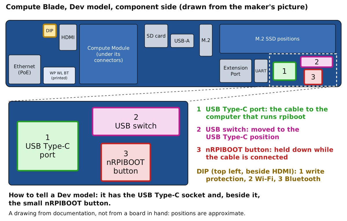
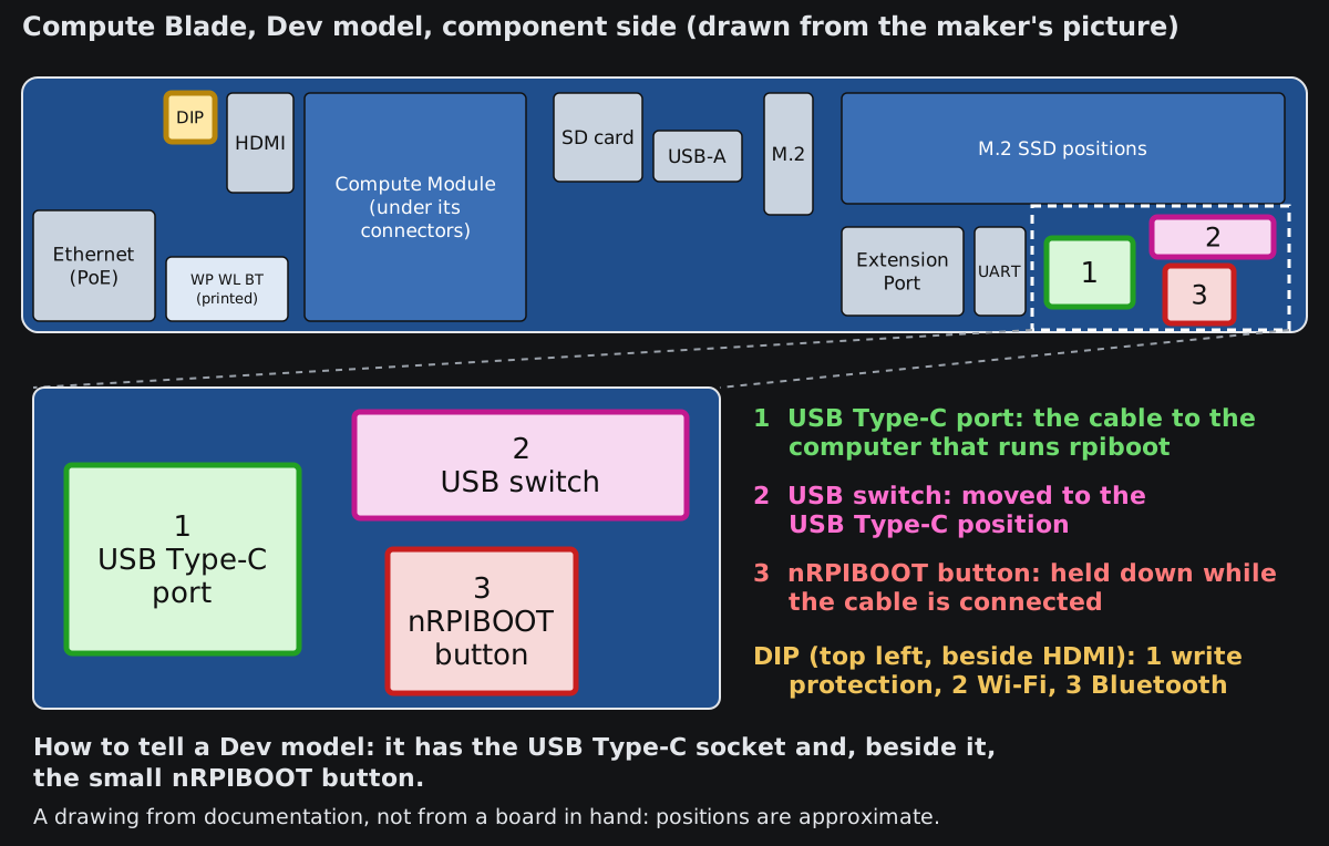
A Compute Module’s bootloader is written over USB from another computer, and that needs the three parts numbered 1, 2 and 3 in the drawing. The blade’s maker says only the Dev model has them. A failed write on a Compute Module can be repaired only the same way, which is why a blade that works is left alone.
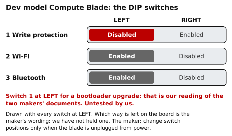
The Dev model also has the switch that holds the bootloader’s write protection.
What the Compute Blade’s maker documents
Warning
Untested by us. Do not follow these as steps.
Only the Dev model of the Compute Blade has the parts for the USB route. The maker says so where it describes writing an operating system to a module’s eMMC, in a guide written for the Compute Module 4 (image guide); the same port and button are what a bootloader flash over USB needs:
eMMC can only be imaged on Dev blade as it has USB Type-C port, USB switch, and nRPIBOOT button
and, for putting the module into USB boot:
From the usbboot directory run
sudo ./rpibootMove the USB switch to the USB Type-C position. Then, while holding down the nRPIBOOT button on the blade connect the USB Type-C cable.
The Device will reconnect several times. On the last time it will appear as a USB media device.
The USB switch is there
because “The compute module can only operate one USB port at a time.” The
maker’s usbboot guide
covers building rpiboot and says the configuration is edited in
/usbboot/<firmware directory>/config.txt; for the flash itself it points to
Raspberry Pi’s “Flash Compute Module bootloader EEPROM”, which is the procedure
printed again below.
The write-protect pin is on a DIP switch, again on the Dev model only. From the maker’s DIP switch guide:
DIP Switch is ONLY populated on Dev model Compute Blades.
Only change switch positions when the Blade is unplugged from power.
To enable write protection, changes are required to
config.txt. It can be found in the directory/boot/firmware/, or flash the EEPROM using usbboot adding the following line to theconfig.txtfileeeprom_write_protect=1This will pull theEEPROM_nWPpin low. This will enable the DIP switch.
Read with Raspberry Pi’s description (quoted below), that is the same two-part lock:
eeprom_write_protect=1 sets the flash’s status register, and switch 1 is what
holds EEPROM_nWP low. Raspberry Pi requires EEPROM_nWP not to be low while
the bootloader is flashed, and the maker’s table calls the left position
“Disabled”, so left is the position for an upgrade. That last step is our
inference from the two documents, not something either states or we have tried.
What is not known about the blade
Which model the blades at ps1 are. We have not recorded it. The maker’s pages name a Dev model and a TPM model. On a blade that is not a Dev model the maker describes no USB Type-C port, no nRPIBOOT button and no DIP switch, so, as far as those pages go, neither the USB route nor the hardware lock exists on the blade itself; the module would then have to go into a carrier that has them (Raspberry Pi describes the route on its own IO boards), which we have not done.
What a blade without the DIP switch does with
EEPROM_nWP(tied low, tied high or left open). The maker’s pages we read do not say.Whether a blade’s bootloader can be updated from the running system. Raspberry Pi’s self-update needs update files in the boot file system it booted from (“For network boot make sure that the TFTP
bootdirectory can be mounted through NFS and thatrpi-eeprom-updatecan write to it”), and it “does not update the bootloader atomically”. On a netboot root like ps1’s, a read-only export under a tmpfs overlay, a file written on the blade never reaches the boot directory the bootloader reads, so we expect it not to work there. Not tried by us on any Compute Module.
What Raspberry Pi documents for a Compute Module
Warning
Untested by us on this hardware. Do not follow these as steps on a blade: they are written for Raspberry Pi’s own IO boards.
Warning
Not yet run by us on this hardware. Everything in this section is Raspberry
Pi’s documentation, quoted from
raspberrypi/documentation at
commit 287523e6. No fpgas.online Compute Module has had its bootloader
upgraded or locked by this procedure. Read the bootloader state first (the
vcgencmd commands above work on a Compute Module; the device node of the boot
flash and its part have not been read by us on a CM4 or CM5).
The SD card route above does not exist on a Compute Module. From Compute Module EEPROM bootloader:
On Compute Modules with an EEPROM bootloader, ROM never runs
recovery.binfrom SD/eMMC. These Compute Modules disable therpi-eeprom-updateservice by default, because eMMC is not removable and an invalidrecovery.binfile could prevent the system from booting.You can override this behaviour with
self-updatemode. Inself-updatemode, you can update the bootloader from USB MSD or network boot.WARNING:
self-updatemode does not update the bootloader atomically. If a power failure occurs during an EEPROM update, you could corrupt the EEPROM.
and from the Pi boot EEPROM page: “Reflashing the bootloader over USB is also the only option available for CM4 and CM4S.”
Flashing the bootloader over USB (rpiboot).
This needs a second computer with
rpiboot (sudo apt install rpiboot,
or built from source), a USB cable to the carrier’s USB device port, and the
carrier’s nRPI_BOOT jumper or button, which makes the module wait for a USB
host instead of booting. Raspberry Pi describes it for its own IO boards (“Fit
nRPI_BOOT to J2 (disable eMMC Boot) on the IO board jumper”); another
carrier brings nRPI_BOOT and the USB device port out in its own way, to be
looked up in that carrier’s documentation.
To flash the bootloader EEPROM:
Set up the hardware as you would when flashing the eMMC, but ensure
EEPROM_nWPis not pulled low.Run the following command to write
recovery/pieeprom.binto the bootloader EEPROM:./rpiboot -d recoveryWhen complete,
EEPROM_nWPcan be pulled low again.
Setting the configuration and the lock.
To modify the Compute Module EEPROM bootloader configuration:
Navigate to the
usbboot/recoverydirectory.If you require a specific bootloader release, replace
pieeprom.original.binwith the equivalent from your bootloader release.Edit the default
boot.confbootloader configuration file to define aBOOT_ORDER: For network boot, useBOOT_ORDER=0xf2. For SD/eMMC boot, useBOOT_ORDER=0xf1. For USB boot failing over to eMMC, useBOOT_ORDER=0xf15. For NVMe boot, useBOOT_ORDER=0xf6.Run
./update-pieeprom.shto generate a new EEPROM imagepieeprom.binimage file.If you require EEPROM write-protection, add
eeprom_write_protect=1to/boot/firmware/config.txt. When enabled in software, you can lock hardware write-protection by pulling theEEPROM_nWPpin low.Run the following command to write the updated
pieeprom.binimage to EEPROM:../rpiboot -d .
So on a Compute Module the lock has two parts, as on the Pi 4: the status
register, set by eeprom_write_protect=1, and the EEPROM_nWP pin of the
module’s connector, which the carrier must pull low for the status register to
stay as set. Raspberry Pi’s step 5 names /boot/firmware/config.txt while step
6 flashes from the usbboot/recovery directory, which has a config.txt of its
own; which of the two the setting has to be in is not clear from the text and
not tried by us. Whether a given carrier pulls EEPROM_nWP low, leaves it open or
brings it to a jumper is a property of that carrier. For the upgrade it must
not be low; for the lock it must be.
Differences from the Pi 5.
No card route and no
recovery.binfrom storage. Raspberry Pi names USBrpibootas the only way to reflash a CM4; for a CM5 we infer the same from the passage above. A Compute Module whose bootloader is broken therefore needs its carrier’s USB device port andnRPI_BOOT.Self-update over netboot exists but “does not update the bootloader atomically”: a power cut during the write can leave a module that only
rpibootrepairs.Our Pi 5 finding that a protected flash ignores a netboot self-update silently (observation 3) may hold here too: read the version after any upgrade.
Sources
Measurements: fpgas.online fleet at Welland, 3, 4 and 6 Oct 2026, Pi 5.
Raspberry Pi documentation, commit
287523e6:computers/config_txt/boot.adoc,computers/raspberry-pi/boot-eeprom.adoc,computers/raspberry-pi/eeprom-bootloader.adoc,computers/compute-module/cm-bootloader.adoc,computers/compute-module/cm-emmc-flashing.adoc.Winbond W25Q16JV datasheet (status register bits,
/WPandQE).Compute Blade documentation (Uptime Lab), read 5 Oct 2026: getting-started/image, guides/dip, guides/usb, advanced-guides/usbboot.
Bootloader reads of two Compute Blades at ps1 (Compute Module 5 Lite), 5 Oct 2026.
Figures:
docs/setup/bootloader-eeprom/make_figures.pyin this repository draws them. The photographs are crops of “Raspberry Pi5 8GB Bottom View (1).jpg” by Suyash Dwivedi, Wikimedia Commons, CC BY-SA 4.0; the annotated versions are under the same licence.Step 1 as run: raspberrypi/rpi-eeprom at commit
a72213d, 5 Oct 2026, on a PC.
.jpg)