How to fit the cables and the card (Compute Blade)
Your two cables for an Acorn on a Compute Blade have passed the bench check, and you are fitting them and the card.
This procedure is waiting for its bench run: issue #219.
Photos: Uptime Lab (Compute Blade), RHS Research (LiteFury underside; the Acorn is the same PCB).
What you need
Parts
both cables, checked on the bench (How to check the cables on the bench (Compute Blade))
the Acorn
the Compute Blade
M2x2.5 screw, from the Compute Blade’s box
M2x2.5 standoff, from the Compute Blade’s box
M2 nylon washer, from the Compute Blade’s box
Tools
a PH1 (Phillips size 1) screwdriver
a 5 mm hex driver, only if the standoff is missing
Steps
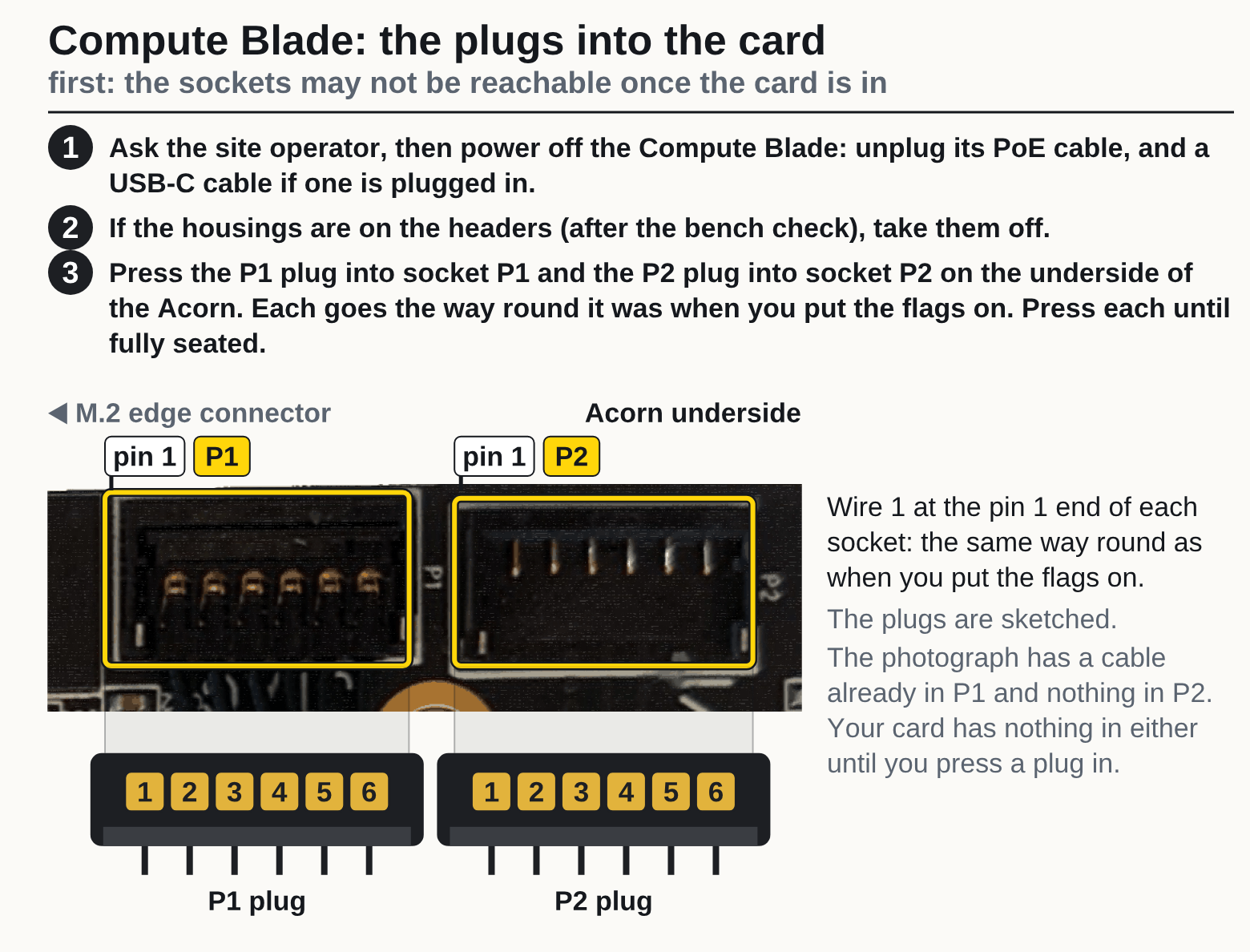
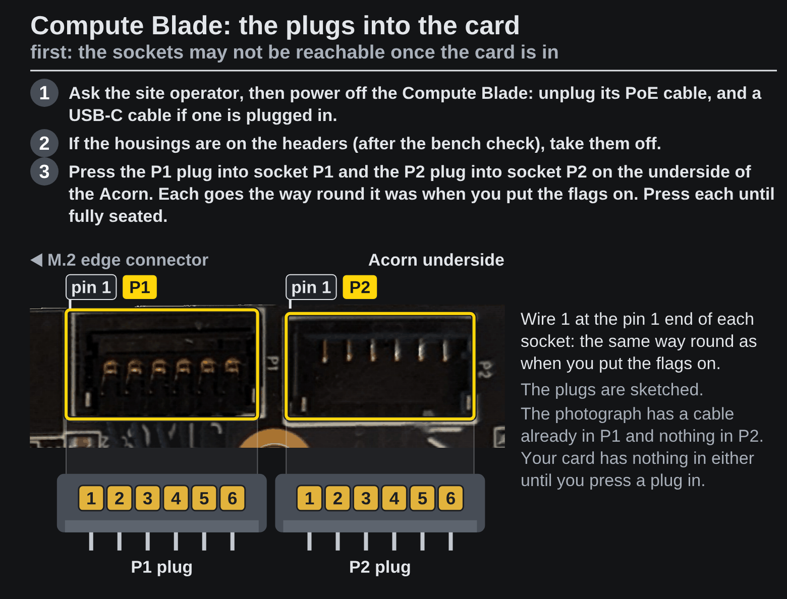
1. Fit the plugs into the card. The sockets are on the underside of the card and may not be reachable once it is in the slot. So the plugs go in first, in this order. After action 1, touch bare metal of the host before you pick up the card, and hold it by its edges.
Ask the site operator, then power off the Compute Blade: unplug its PoE cable, and a USB-C cable if one is plugged in.
If the housings are on the headers (after the bench check), take them off.
Press the P1 plug into socket P1 and the P2 plug into socket P2 on the underside of the Acorn. Each goes the way round it was when you put the flags on. Press each until fully seated.
2. Fit the card, then the housings, in this order. How the card goes in (action 4) is from the Compute Blade’s assembly guide.
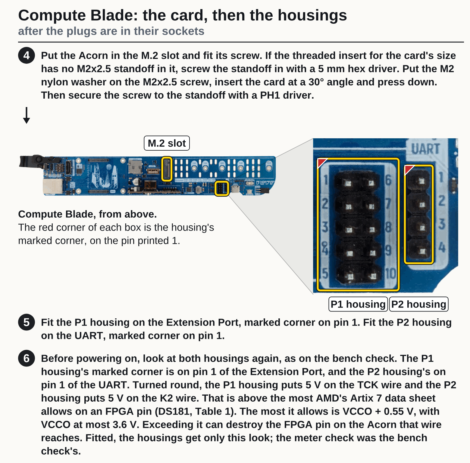
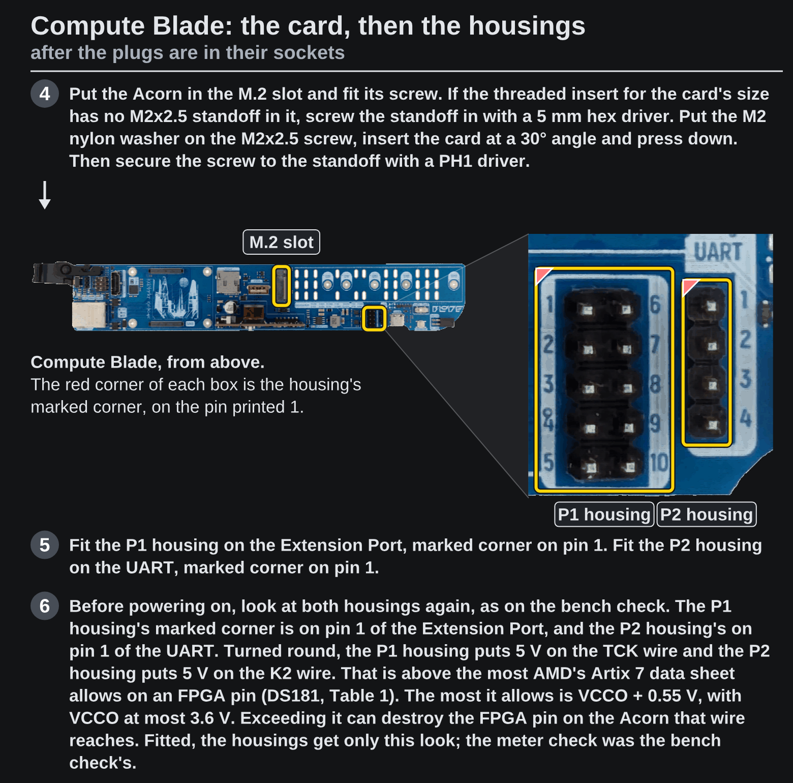
Put the Acorn in the M.2 slot and fit its screw. If the threaded insert for the card’s size has no M2x2.5 standoff in it, screw the standoff in with a 5 mm hex driver. Put the M2 nylon washer on the M2x2.5 screw, insert the card at a 30° angle and press down. Then secure the screw to the standoff with a PH1 driver.
Fit the P1 housing on the Extension Port, marked corner on pin 1. Fit the P2 housing on the UART, marked corner on pin 1.
Before powering on, look at both housings again, as on the bench check. The P1 housing’s marked corner is on pin 1 of the Extension Port, and the P2 housing’s on pin 1 of the UART. Turned round, the P1 housing puts 5 V on the TCK wire and the P2 housing puts 5 V on the K2 wire. That is above the most AMD’s Artix 7 data sheet allows on an FPGA pin (DS181, Table 1). The most it allows is VCCO + 0.55 V, with VCCO at most 3.6 V. Exceeding it can destroy the FPGA pin on the Acorn that wire reaches. Fitted, the housings get only this look; the meter check was the bench check’s.
Check
Both housings sit on the pins action 5 names, each marked corner on its pin, as action 6 looks for before power.
If it fails
A housing is off its pins, or turned round: do not power on. Take it off and fit it again as action 5 says.
Next
Ask the site operator, then power the Compute Blade on and run the check: How to run the Acorn check on a Compute Blade.